
30 August 2024

Abstract
In this study, we present the aerodynamic advantages of morphing wings. We studied the seamless trailing edge morphing flap to determine its optimum configuration for different flight conditions, including climb, cruise and gliding descent. A comparative study was also conducted between a wing equipped with morphing flap and a wing with conventional hinged flap. The optimization was performed by specifying and analyzing a certain objective function and the flight performance goal for each flight condition. Increasing the climb rate, extending the flight range and endurance in cruise, and decreasing the descent rate are the flight performance goals covered in this study. It was shown that by using an optimum configuration for the morphing wing in climb condition, the required power could be reduced by up to 3.8%, and climb rate increased by 6.13%. The comparative study also revealed that the morphing wing enhanced aerodynamic efficiency by up to 17.8% and extended the laminar flow. Finally, the optimum configuration for the gliding descent brought on a 43% reduction in the descent rate.
Keywords: Seamless morphing trailing edge flap; aerodynamic optimization; UAS-S45;
A Bio-Inspired Environmentally Friendly Morphing Wing
The aeronautics industry has a significant impact on greenhouse gas emissions as thousands of airplanes—ranging from personal aircraft to commercial and military jets—fly every day. This huge number of daily flights contributes to large amounts of CO2 emissions into the atmosphere. This fact was highlighted during the COVID-19 pandemic, with satellite images of CO2 emissions before and during the pandemic showing a considerable decrease in CO2 emissions [1]. According to the Carbon Global Project [2], the drop in flights dramatically reduced carbon emissions during the world-wide lockdown compared to other sources, including land transport and industry. Their findings indicate that during the peak of the world-wide lockdown (March, April, and May 2020), the 75% reduction in air traffic accounted for 60% of the carbon emission reduction, while land transport accounted for a 36% reduction (second after aviation), or nearly half [2]. Carbon emission reduction is therefore among the highest priorities in the aeronautics industry due to its undeniable impact on climate.
In aerodynamics, morphing wing technology has shown great potential in next generation environmentally friendly aircraft, due to its success in improving aircraft performance by reducing drag and fuel consumption, as well as aircraft weight [3, 4]. While most of these studies are still at the conceptual level due to structural limits, ongoing research in aerodynamics and at a structural level have shown a promising future for this technology. Many morphing approaches have been examined over the past few decades from sweep [5], twist [6, 7], winglet [8, 9] and span morphing [10], to camber [11-14], chord [15], leading edge [16-18] and upper surface [19-28] morphing. However, among these approaches, trailing edge morphing [29] has received considerable attention due to its substantial impact in improving flight performance and reducing fuel consumption.
In this paper, the seamless morphing flap was optimized using a high-fidelity gradient-based methodology applied to three main flight phases including climb, cruise and descent, with specified objective functions for each flight condition. For the climb condition, the aim was to find the optimum deflection of the SMTE flap to maximize climb rate for the cruise flight, for which the main objectives were range and endurance maximization. For the descent flight, the main objective was to reduce the descent rate with the SMTE flap morphing.
The SMTE Flap
Eliminating the gap between the wing and its edge flaps brought many advantages in terms of reducing flow turbulence around the junctions by extending laminar flow, reducing drag and noise, thus generating more lift force. Therefore, sealing the gaps in trailing edge flaps—which are considered the main control surfaces on a wing—and generating a smooth flap deformation will unquestionably improve the wings’ aerodynamic performance.
In this study, the SMTE flap was examined for the entire flight envelope of the UAS-S45, to find its optimum deformation for each flight condition. Figure 1 illustrates the SMTE flap. As indicated, the SMTE flap covers 30% of the chord length and 41% of the wings’ semi-span by including its transition sections (Figure 1).

Figure 1. Schematics of a Seamless Morphing Trailing Edge (SMTE) flap.
Overview of the Optimization Strategy
Given that the main goal of this study is the aerodynamic optimization of the SMTE flap, a high-fidelity optimization was conducted to obtain the optimum morphing configuration in different flight conditions, including climb, cruise and descent. This optimization is performed separately for each flight condition with its specified objective function. The gradient-based optimization is coupled with the discrete adjoint method in conjunction with the high-fidelity flow solver OpenFOAM. This process generates the UAS-S45 wing design using the Free-Form Deformation (FFD) parametrization method. In this optimization framework, a high-level interface was established between the OpenFOAM layer and Python libraries. Figure 2 illustrates the overall optimization process, in which the OpenFOAM and Python layers are specified with different colors.

Figure 2. The overall optimization framework.
Objectives of the Study
This study aims to find the optimum configuration of the SMTE flap for the entire flight envelope, including climb, cruise and descent. Each flight condition has different objective functions, characterized by specific goals, as summarized in Table 1. Figure 3 illustrates the entire flight envelope for UAS-S45. Although the objective function for each flight condition is different, the overall optimization framework is the same for all.
Table 1. Specific goal, and objective function for each flight condition, climb, cruise and descent.


Figure 3. The entire flight envelope of the UAS-S45.
Key Findings
Climbing Phase
In a climbing flight, the main goal is to increase altitude, in other words, to convert the aircraft’s kinetic and internal energy into potential energy to overcome the aircraft’s weight. During a straight and level flight, the required energy is provided by the engines at a specified speed. However, to increase potential energy (altitude) at the same speed, extra power is required. The amount of extra power determines the rate at which altitude is increased [32]. The added power is the difference between the power required for level flight and the engine’s available power. Figure 4 shows the balance of aerodynamic forces for the UAS-S45 in climb condition. By minimizing the objective function for climb (Table 1), the SMTE is optimized for this flight condition. Table 2 compares the morphing wing with a conventional wing in terms of climb rate and required engine power, where results show a 6.13% increase in climb rate and a 3.8% decrease in required engine power compared to a clean wing without deformation.

Table 2. Comparison of the UAS-S-45 wing with and without an SMTE flap in a climbing flight.

Cruise Phase
In this study, the cruise flight objective function is divided into the optimization of both range and endurance. The objective function in terms of range improvement is the maximization of the lift-to-drag ratio. Our results obtained from aerodynamic parameters, including lift, drag and lift-to-drag ratio show the need to deploy an SMTE flap, due to its substantial improvement in aerodynamic performance over a clean wing and a wing with deflected hinged flaps (Fig. 5).

Figure 5. Comparison between the aerodynamic performance of the wing with an SMTE flap, hinged flap, and baseline clean wing configurations for various angles of attack; a) lift coefficient, b) drag coefficient, c) lift-to-drag ratio, d) flap vertical deflection magnitude.
As shown in Figure 5-c, the overall aerodynamic performance of the wing with an SMTE flap has increased compared to the hinged flap configuration. While the drag with an SMTE flap is higher than that of the hinged flap at some angles of attack (Fig. 5-b), this drag penalty is compensated by the increased lift generation, which results in the overall improvement of aerodynamic efficiency by up to 33% compared to a clean wing, and 17.8% compared to a hinged flap, respectively (Fig. 5-c). Figure 6 schematically compares flow laminarity between hinged and morphing wings, showing the extended flow laminarity for the morphing wing.

Figure 6. Comparison of an SMTE flap (right) with a hinged flap (left) for a cruise flight in terms of airflow laminarity.
In addition, Figure 7 illustrates the whole UAS-S45 equipped with an SMTE flap on the right wing and a hinged flap on the left wing to obtain a good comparison in terms of pressure variations, as detailed in Figure 7 (a to c).


Figure 7. The UAS-S45 equipped with an SMTE (right) and a hinged flap (left), with their pressure coefficient distribution presented in both chordwise (a and b), and c) spanwise directions.

Figure 8. Pressure contours of a UAS-S45 with a hinged flap and an SMTE flap, from a) top view, and b) bottom view.
The pressure coefficient distribution in both chordwise and spanwise directions in Fig. 7 (a), (b) and (c) clearly shows the pressure peaks around the gaps for the hinged flap, whereas for the SMTE flap, these pressure peaks have been eliminated, leading to very smooth pressure variations. These pressure peaks occur mainly because of the flow spillage from the pressure side to the suction side due to the gaps on the hinged flap.
In addition, both the chordwise and the spanwise pressure diagrams (Fig. 7 (a-c)) show that for the SMTE flap, the pressure gap between the upper and lower surface of the wing is higher than that of the hinged flap, which leads to the increased lift generation. Eliminating the gaps in the SMTE flap extends the laminar flow on the upper surface of the wing, whereas for the hinged flap, the low-pressure contour is stopped at the start of the gap (Fig. 8-a).
As another objective function of the cruise condition, endurance optimization mainly concerns flight time, as most of it is dedicated to cruise flight conditions. Depending on the engine type, the relationship between endurance and aerodynamic properties (lift and drag) differs.
Figures 9 (a to d) show the aerodynamic parameters obtained with the SMTE flap after optimization. These parameters are compared to those of a clean wing, i.e., with no flap deflection
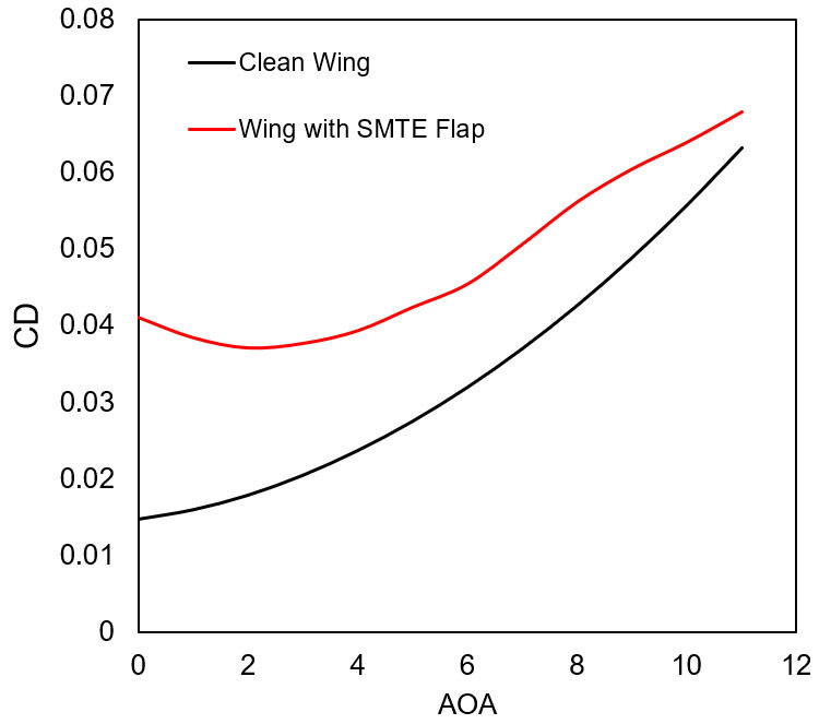


Figure 9. Performance of the wing with an SMTE flap versus a clean wing for different angles of attack; a) lift coefficient, b) drag coefficient, c) endurance efficiency, d) flap deflection magnitude.
The optimum aerodynamic parameters of an SMTE wing for maximum endurance were obtained for different angles of attack (Fig. 9). As shown in Fig. 9 (a) and (b), for the wing with a flap deformation in a downward direction, both lift and drag are increased, but the lift increase is higher than the drag increase. However, the endurance efficiency diagram (Fig. 9-(c)) shows that the morphing configuration loses its performance at an angle of attack higher than AOA= 7°, after which the performance of both wings is the same, and over this angle, the clean wing performs better than the wing with an SMTE flap as its endurance is higher.
Descent Phase
The last flight condition studied in this paper was the non-powered gliding descent. In a space shuttle, a non-powered or gliding descent—where no engine power is involved in the entire distance from orbit to landing lane—is a normal flight condition. A good equilibrium of the lift, drag and weight is used for landing the shuttle without any need for propulsive forces. Sailplanes are another example of using a gliding descent. Nonetheless, a non-powered descent is not a normal flight condition for most aircraft, and most often occurs only because of engine failure, which calls for emergency measures. In this critical situation, the pilot’s highest priority is to have enough time to prepare for an emergency landing or to restart the engine. Reducing the descent rate is the only option for extending the descent time. Figure 10 shows the aerodynamic force balance in descent.

Figure 10. The UAS-S45 in descent flight conditions with its aerodynamic forces (A) and descent trajectory (B).
The UAS-S45 descent was studied under four different angles of descent, ranging from -5° to -8° with the aim to find the best angle of descent as well as the best angle of deflection for the wing with the SMTE flap versus the clean wing. Figure 11 shows the optimization results of the UAS-S45 wing with an SMTE flap, where the objective function (CD/CL3/2) was minimized for different angles of attack.

Figure 11. Comparison of the descent rate between a clean wing and a wing with an SMTE flap.
As illustrated in Figure 11, for all angles of attack the morphing flap deformation minimized the descent rate (increased the descent time) compared to a wing with no flap. Evaluating the reduction of descent rates, the maximum reduction is achieved in γ=-5°, with its 43% reduction in descent rate, nearly half of the normal descent rate. Figure 12 shows the SMTE flap deformation for each angle of descent.

Figure 12. Optimum configuration of a UAS-S45 wing equipped with an SMTE flap for a gliding descent flight.
Conclusion
This study investigated the seamless morphing trailing edge flap (SMTE flap) for the entire flight envelope of a UAS-S45, including climb, cruise and gliding descent, each having their unique specific flight characteristics. The main objective of this study was to find the optimum configuration of the SMTE flap for these three flight conditions with their corresponding objective functions and goals.
For the climb condition, the goal was to find an optimum configuration to increase the climb rate compared to that of the clean wing configuration, and this goal was accomplished by decreasing the required engine power to its minimum rate.
The cruise flight condition had two objectives expressed in range and endurance improvement, depending on the flight mission objective. The goal was to increase both (range and endurance), and to find the optimum SMTE flap configuration for each one. Regarding range improvement, the SMTE flap was compared with the hinged flap configuration in terms of aerodynamic performance. The SMTE flap outperformed the hinged flap in many aspects, including extension of flow laminarity, reduction of turbulence on the gaps and enhancing overall aerodynamic performance. Then, the optimum configuration and angle of attack were determined to maximize endurance. A 61.2% gain in endurance was achieved for the wing with an SMTE flap compared to the clean wing configuration.
Finally, the gliding descent phase was studied with the purpose of reducing the descent rate using an SMTE flap. The maximum descent rate reduction for the morphing wing compared to a baseline wing was up to 43% for γ =-5° . The minimum magnitude of the descent rate was achieved for γ =-6°, which was chosen as the optimum angle of attack for the gliding descent.
Additional Information
For more information on this research, please read the following paper:
Mir Hossein NEGAHBAN, Musavir BASHIR, Victor TRAISNEL, Ruxandra Mihaela BOTEZ, Seamless morphing trailing edge flaps for UAS-S45 using high-fidelity aerodynamic optimization, Chinese Journal of Aeronautics, Volume 37, Issue 2, 2024, Pages 12-29, ISSN 1000-9361, https://doi.org/10.1016/j.cja....
References
[2] Le Quéré C, Jackson RB, Jones MW, et al. Temporary reduction in daily global CO 2 emissions during the COVID-19 forced confinement. Nature climate change 2020; 10(7):647-53.
[3] Dimino I, Lecce L, Pecora R. Morphing wing technologies: Large commercial aircraft and civil helicopters: Butterworth-Heinemann, 2017.
[4] Ameduri S, Concilio A. Morphing wings review: aims, challenges, and current open issues of a technology. Proceedings of the Institution of Mechanical Engineers, Part C: Journal of Mechanical Engineering Science 2020:0954406220944423.
[5] Muhammad Umer H, Maqsood A, Riaz R, Salamat S. Stability characteristics of wing span and sweep morphing for small unmanned air vehicle: a mathematical analysis. Mathematical Problems in Engineering 2020; 2020.
[6] Segui M, Botez RM. Evaluation of the impact of morphing horizontal tail design of the UAS-S45 performances. 2019.
[7] Ismail N, Zulkifli A, Abdullah M, Basri MH, Abdullah NS. Optimization of aerodynamic efficiency for twist morphing MAV wing. Chinese Journal of Aeronautics 2014; 27(3):475-87.
[8] Segui M, Abel FR, Botez RM, Ceruti A. New aerodynamic studies of an adaptive winglet application on the Regional Jet CRJ700. Biomimetics 2021; 6(4):54.
[9] Liauzun C, Le Bihan D, David J-M, Joly D, Paluch B. Study of morphing winglet concepts aimed at improving load control and the aeroelastic behavior of civil transport aircraft. Aerospace Lab 2018(14):1-15.
[10] Ajaj R, Friswell M, Saavedra Flores E, Little O, Isikveren A. Span morphing: a conceptual design study. 53rd AIAA/ASME/ASCE/AHS/ASC structures, structural dynamics and materials conference 20th AIAA/ASME/AHS adaptive structures conference 14th AIAA. 2012; 1510.
[11] Communier D, Botez RM, Wong T. Design and validation of a new morphing camber system by testing in the price—Païdoussis subsonic wind tunnel. Aerospace 2020; 7(3):23.
[12] Negahban MH, Botez RM, Razavi SE. New Method for the Flow Modeling around chord-wise Morphing Airfoil. AIAA SCITECH 2022 Forum. 2022; 2574.
[13] Razavi SE, Negahban MH. Numerical Investigation of Flow Behavior Around Chordwise Morphing NACA 0012. Amirkabir Journal of Mechanical Engineering 2020; 51(6):1411-26.
[14] Yuzhu L, Wenjie G, Jin Z, Zhang Y, Donglai Z, Zhuo W, Dianbiao D. Design and experiment of concentrated flexibility-based variable camber morphing wing. Chinese Journal of Aeronautics 2022; 35(5):455-69.
[15] Negahban MH, Bashir M, Botez RM. Aerodynamic Optimization of a Novel Synthetic Trailing Edge and Chord Elongation Morphing: Application to the UAS-S45 Airfoil. AIAA SCITECH 2023 Forum. 2023; 1582.
[16] Bashir M, Longtin-Martel S, Botez RM, Wong T. Optimization and design of a flexible droop-nose leading-edge morphing wing based on a novel black widow optimization algorithm—part I. Designs 2022; 6(1):10.
[17] Bashir M, Longtin-Martel S, Zonzini N, Botez RM, Ceruti A, Wong T. Optimization and Design of a Flexible Droop Nose Leading Edge Morphing Wing Based on a Novel Black Widow Optimization (BWO) Algorithm—Part II. Designs 2022; 6(6):102.
[18] Zi K, Daochun L, Tong S, Xiang J, Zhang L. Aerodynamic characteristics of morphing wing with flexible leading-edge. Chinese Journal of Aeronautics 2020; 33(10):2610-9.
[19] Koreanschiᵃ A, Gaborᵃ OS, Acottoᵃ J, et al. Optimization and Design of a Morphing Aircraft Wing Tip Demonstrator at Low Speed for Drag Reduction, Part I–Aerodynamic Optimizations Using 3 Algorithms: Genetic, Bee Colony and Gradient Descent. 2017.
[20] Botez RM, Molaret P, Laurendeau E. Laminar flow control on a research wing project presentation covering a three year period. Canadian aeronautics and space institute annual general meeting. 2007.
[21] Sugar Gabor O. Validation of morphine wing methodologies on an unmanned aerial system and a wind tunnel technology demonstrator, École de technologie supérieure, 2015.
[22] Gabor OŞ, Simon A, Koreanschi A, Botez RM. Improving the UAS-S4 Éhecal airfoil high angles-of-attack performance characteristics using a morphing wing approach. Proceedings of the institution of mechanical engineers, Part G: Journal of Aerospace Engineering 2016; 230(1):118-31.
[23] Gabor OŞ, Koreanschi A, Botez R. Analysis of UAS-S4 Éhecatl aerodynamic performance improvement using several configurations of a morphing wing technology. The Aeronautical Journal 2016; 120(1231):1337-64.
[24] Botez R, Koreanschi A, Gabor O, et al. Numerical and experimental transition results evaluation for a morphing wing and aileron system. The Aeronautical Journal 2018; 122(1251):747-84.
[25] Popov AV, Grigorie LT, Botez R, Mamou M, Mébarki Y. Real time morphing wing optimization validation using wind-tunnel tests. Journal of Aircraft 2010; 47(4):1346-55.
[26] Popov AV, Botez RM, Labib M. Transition point detection from the surface pressure distribution for controller design. Journal of Aircraft 2008; 45(1):23-8.
[27] Koreanschi A, Sugar-Gabor O, Acotto J, et al. Optimization and design of a morphing wing tip aircraft demonstrator for drag reduction at low speeds, Part Π–Experimental validation using infra-red transition measurements during wind tunnel tests. Chin J Aeronaut 2017; 30:164-74.
[28] Gabor OŞ, Koreanschi A, Botez RM. A new non-linear vortex lattice method: Applications to wing aerodynamic optimizations. Chinese Journal of Aeronautics 2016; 29(5):1178-95.
[29] Carossa GM, Ricci S, De Gaspari A, Liauzun C, Dumont A, Steinbuch M. Adaptive trailing edge: specifications, aerodynamics, and exploitation. Smart Intelligent Aircraft Structures (SARISTU) Proceedings of the Final Project Conference. 2016; 143-58.
[30] He P, Mader CA, Martins JR, Maki K. An object-oriented framework for rapid discrete adjoint development using OpenFOAM. AIAA Scitech 2019 Forum. 2019; 1210.
[31] He P, Mader CA, Martins JR, Maki KJ. Dafoam: An open-source adjoint framework for multidisciplinary design optimization with openfoam. AIAA journal 2020; 58(3):1304-19.
[32] Marchman JF. Aerodynamics and Aircraft Performance: James F. Marchman, 2004.


