Structural Design Challenge for a C-Class Catamaran
The featured image is from the authors. Substance CC license applies.
Under close scrutiny by researchers for some time now, additive manufacturing finally made its appearance in an industry that can evaluate its potential. This type of shaping process is handy for single-use custom designs, and the RAFALE team wanted to evaluate the structural feasibility of this state-of-the-art technology by integrating it into the second prototype of the C-Class catamaran, at École de technologie supérieure (ÉTS). This article shows the development process of a structural link component resulting from additive manufacturing, whose aim was to join the carbon fibre elliptical tubes that are part of the catamaran’s cross-member. The component, made from an AlSi10Mg aluminum alloy, was shaped using the Laser Powder Bed Fusion (L-PBF) technology (also called Selective Laser Melting or SLM ).
Introduction

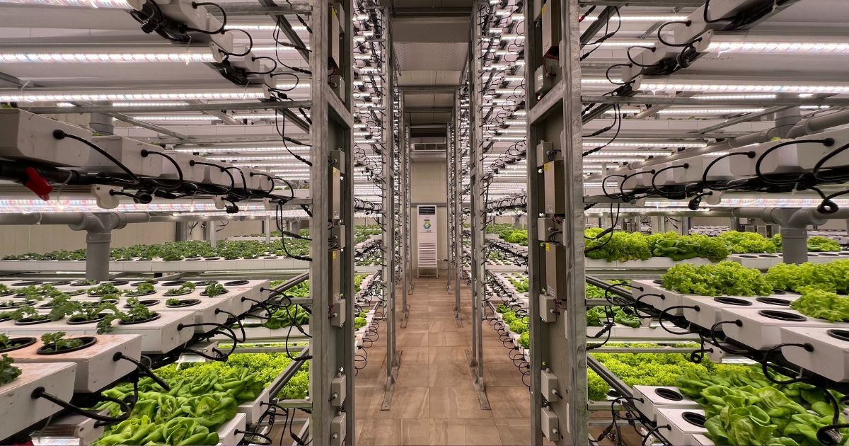
Figure 1 C-Class Catamaran
The simplicity of a C-Class catamaran is based on the quality of its components, allowing it to attain a high level of synergy. To succeed in making a new flying craft, members of the RAFALE team collaborated with the ETS Research Chair on Engineering of Processing, Materials and Structures for Additive Manufacturing and the Shape Memory Alloys and Intelligent Systems Laboratory (LAMSI). The structural challenges posed by additive manufacturing (AM) are significant ones and special knowledge is needed to take full advantage of the method.
C-Class Catamarans
The Rafale team is a scientific and technological club composed of ÉTS students passionate about boating, who practise sport sailing at the university, and who wanted to build their own sail craft. In a bold move, the design of the first ÉTS multihull prototype was launched in 2013. This project proved to be a springboard for their participation in the September 2015 Class-C World Championship, the “Little Cup”.
Over the last 50 years, performances of Class-C catamarans have been steadily improving by taking advantage of a well-known energy resource: the wind! Originally inspired by Pacific pirogues, these craft are now equipped with an aerodynamic-shaped rigid wing and hydrofoils, allowing them to fly above the water and reach speeds of up to 60 km/h. Handled by talented sailors, these sailing prototypes are known to be true platforms for small-scale technological innovation.
Motivated by the experience gained in the 2015 championship, the team wanted to pursue the adventure by creating a new, more competitive version of their sailing prototype: the RAFALE II.
Design and Technological Opportunities

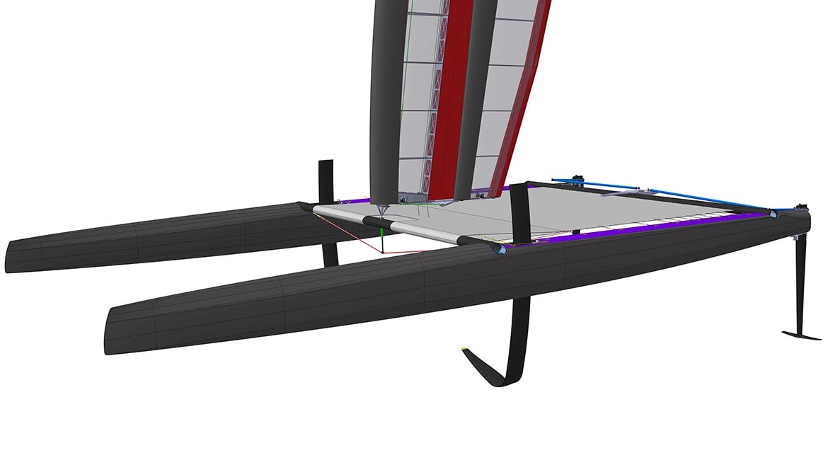
Figure 2 – A: Structural component, B: Front crossbar, C: Martingale, D: Mast foot, E: Tensioner
As a student club, Rafale faces unique challenges, different from those of other “Little Cup” teams. For example, their budget is 26 times lower than that of the winning team of the previous cup: they must therefore make relevant and strategic choices. In addition, to make a high-performance water craft, all components must be perfectly integrated with one another.
As the forward main beam of the future craft will consist of two elliptical carbon fibre prepreg tubes, the challenge lies in making a centre joint that unifies the whole catamaran. This structural connection piece will be the metal core of a composite assembly that will support the wing, bind the hulls and provide rigidity to the platform.
At this stage, additive manufacturing is much more appropriate than traditional manufacturing processes since it reduces manufacturing times as well as demand on the team’s available resources. But above all, this technology has made it possible to optimize the catamaran structure by merging some parts of the final product.
An Iterative Collaborative Process

Figure 3 – Cross-section view of the part during the design process; from the preliminary version (left) to the final version (right). The major evolving features are identified by colour: internal cavities in yellow, hydrofoil attachments in blue, adjustment pole assembly hole in green.
With additive manufacturing, almost any conceivable geometry can be produced. On the other hand, rigorous design is necessary because of the many factors that influence the mechanical properties of the final component. For example, internal micro cracks caused by metal oxidation may occur during the melting process (1). These characteristics must be taken into account during the design process. For a C-Class catamaran, a static value of 15,000 N of compression from the rigid wing to the mast base is a good starting point. Add to this platform tension loads, hull torsion, weight of the crew and potential loading of the craft. Considering the manufacturing method, the properties of the AlSi10Mg aluminum alloy (70 GPa E“Young's modulus, also known as the elastic modulus, is a measure of the stiffness of a solid material. It is a mechanical property of linear elastic solid materials. It defines the relationship between stress (force per unit area) and strain (proportional deformation) in a material.” Wikipedia, 230 MPa YS“Beyond the elastic limit, permanent deformation will occur. The elastic limit is therefore the lowest stress at which permanent deformation can be measured.” Wikipedia, 12% elongation at break), and the resulting loads on the component link, a maximum static stress of 100 MPa was established.

Figure 4 – From left to right:
1- Beginning of the design process based on topological studies.
2- Perspective view of the final digital model.
3- Representation of forces and moments defining the assembly details.
4- Potential constraints on the component.
Inspired by a topological study using the Altair hyperWorks software, the final model is mainly hollow with walls that evolve according to the internal constraints of the component. Stiffeners have been added in order to reflect expected movements of the carbon fibre tubes (non-linear combined movements of 5.3 cm). The outer surface, which looks something like a golf ball, provides the specifications required for adhesive assembly.
Additive Manufacturing of the link Component

Figure 5 – Recovery of link components after the selective laser melting process
The AM technology used to manufacture the link component is to fuse metal powder particles with a laser (2). This way, the three-dimensional object is the result of superposing multitude of metal layers, each with the thickness of a human hair (50 to 100 microns).
Model preparation for production is critical and is used to evaluate the elements that will have an impact on the final result. To prepare for the machining and anodizing tests, two copies of the component were made vertically. Although this orientation took more time to print, it reduced the number of supports to be integrated in the model. Supports are needed during the process to prevent any collapsing of the geometry while diffusing heat. Finally, the component, with a final mass of 1200 g, was heat-treated at 300° C for 2 hours in order to release the residual stresses generated during the process.
Conclusion

Figure 6 – Finished product: the structural link component
In short, knowledge of additive manufacturing among the team is acquired through experience. Made from acrylonitrile styrene acrylate (ASA), the structural web of the rudders (used to operate the catamaran) was also produced using the AM method. In this context, the process was the extrusion and shaping of material (FDM) using a Stratasys 900mc machine. Although the design is complete and manufacturing is still ongoing, team members would like to participate in Miami’s “Foiling Week” competition, from February 15 to 22, 2018.
Acknowledgements
The authors wish to thank Julien Chaussée and Louis Chevallier for their support and expertise in the development of numerical models for finite element analysis, and Gabriel Caron for his participation in the design process. They also wish to thank the active members of the summer 2017 RAFALE team for their commitment.