Bringing Accuracy to Industrial Robots
Ilian Bonev, Professor in the Department of Automated Production Engineering at the École de technologie supérieure (ÉTS), is conducting research in several areas of robotics. He holds the Canada Research Chair in Precision Robotics, and is also responsible for CoRo, the Control and Robotics Laboratory, where Professor Vincent Duchaine, holder of the Lean Robotics Chair, also works. CoRo is undoubtedly one of the best equipped university laboratories in industrial robots and metrology devices. Graduate students and CoRo researchers use more than a dozen industrial robots and many measuring devices.
This article presents precision robotics, one of Professor Bonev’s main research areas. A series of articles will follow, presenting his other research activities with more in-depth coverage of a few of them.
Accuracy vs Repeatability
The concept of precision is often confusing when applied to robotics. Indeed, the terms ” accuracy” and “repeatability” are not the same thing. Repeatability is the average deviation in the effector pose (position and orientation) when the robot’s end-effector returns to a given pose. Accuracy is the error between the controlled (desired) position and the actual position of the robot effector.
Since most industrial robots are relatively rigid, and use zero-backlash gear trains and high-precision encoders, the position repeatability of an industrial robot can easily reach 0.020 mm and even 0.005 mm. Take, for example, a mosquito whose stinger is about 0.020 mm in diameter. If a robot is taught to hold the mosquito and touch its stinger to the stinger of another mosquito, the robot will be able to do so over and over again, thousands of times. On the other hand, if the same industrial robot is programmed to touch the stinger of a mosquito that is exactly one meter away from the first mosquito, the robot will not be able to even come close enough tothe mosquito. Indeed, by default, the accuracy of an industrial robot is in the order of a few millimeters.
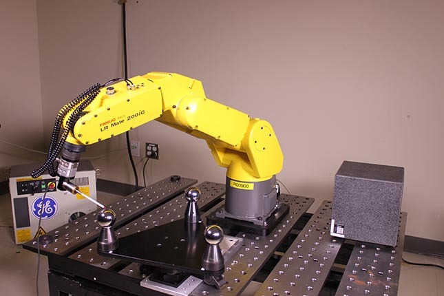
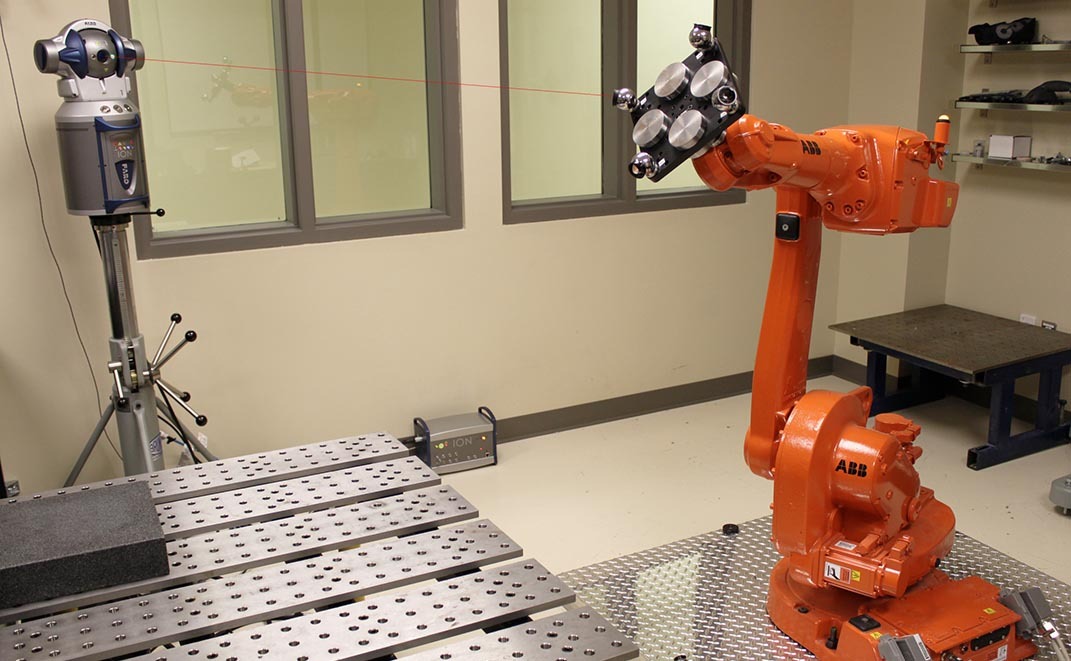
Figure 1 Example of calibration method
Robots Sometimes Need Accuracy
In robotics, accuracy is not always necessary. If a robot can be manually “taught” all the positions its effector must attain, a robot with good accuracy is not necessary. On the other hand, if you want to program a robot to move its effector into calculated positions or those generated from a CAD model, accuracy is paramount. A specific example of such an application would be a robot that has to drill hundreds of holes according to a grid.
Poor accuracy in industrial robots is caused by several factors, the most important being manufacturing errors, assembly errors and elasticity in gear trains. These errors vary from one robot to another. Variations are observed among robots of identical models, and even among robots from the same production batch. The values for various angles, distances, and stiffness used in the mathematical model embedded in each robot controller are nominal values (those for a perfect robot).
Unfortunately, it is not possible, or at least practical, to measure the actual values of these parameters directly. Instead, they must be identified indirectly by measuring the pose or part of the pose (e.g. position) of the robot effector using a metrology device in some fifty or so different configurations and calculating values for these parameters that minimize positioning errors (see the following video). The entire identification process, described in the next section, is called calibration.
Video 1 Robot calibration using a laser tracking device
Robot Calibration
Most industrial robots manufacturers (ABB, KUKA, FANUC, etc.) offer the option of calibrating their robots in the factory before delivery to the customer. Typically, these companies use a laser tracker for calibration, which measures the position of a special reflector attached to the robot effector (header photo). device laser tracker can cost in excess of US $100,000, but the real disadvantage of calibrating the robot at the factory is that it does not make the robotic cell more precise, only the robot. To make a robotic cell more precise, it is necessary to know the exact location of a station or part relative to the robot base, and the location of a tool relative to the robot’s mechanical flange. However, these locations are often very difficult if not impossible to measure directly, especially once the cell is installed. For example, the tool may be a 3D scanner and the part to be scanned could be a section of an already assembled aircraft.
It should be noted that since accuracy and robot calibration are poorly understood notions, the need to calibrate a robotic cell is often only discovered once the cell is completely installed or even in production. Since robots are often used to perform repetitive or similar tasks, it is possible to avoid calibrating a robotic cell by making many manual adjustments on the robot’s path. Companies decide to calibrate in order to minimize the time spent making these adjustments and the resulting waste of test parts.
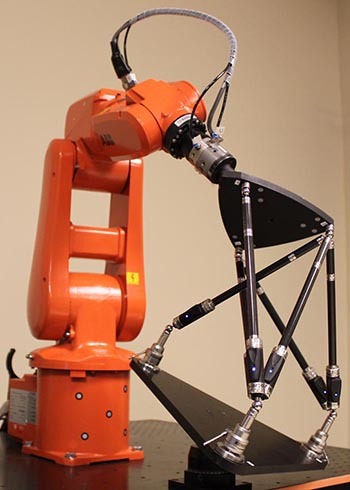
Figure 2 Image of six photographs on a calibration process using a Renishaw ballbar
However, robot manufacturers do not necessarily offer on-site calibration services, especially when dealing with crowded robotic cells equipped with special tooling (e.g., ultrasonic probe or a complex 3D printing head) or organizations located in remote areas. In addition, it is often impossible to use a laser tracker to calibrate robotic cells (for example, when there are vibrations in the floor, or air drafts).
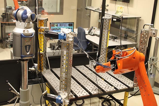
Figure 3 Cable robot used for calibration
Adapted and Affordable Methods
Professor Bonev and his team specialize in robot and robotic cell calibration, using measurement tools that are less costly, sturdier and portable, or that enable automated calibration. Consequently, the team has worked on a calibration method for robots already equipped with a probe and requiring only the addition of an artifact, such as a granite cube or a set of precision spheres (video 2).
Video 2 Robot calibration using a touch probe and datum tube
Professor Bonev has also invented an economical but highly accurate method to measure the robot effector pose in some seventy different locations using a single Renishaw telescopic ballbar (video 3), a standard measuring device in the machine tool field.
Video 3 Manual robot calibration using a single Renishaw telescopic ballbar
The CoRo team has also developed robot calibration methods that use optical systems from Creaform. These systems can measure the poses of several objects at the same time, and they are not affected by vibrations. Finally, a very promising method has been designed for the automated calibration of industrial robots using a new, highly accurate and inexpensive 3D measuring device (Figure 4).
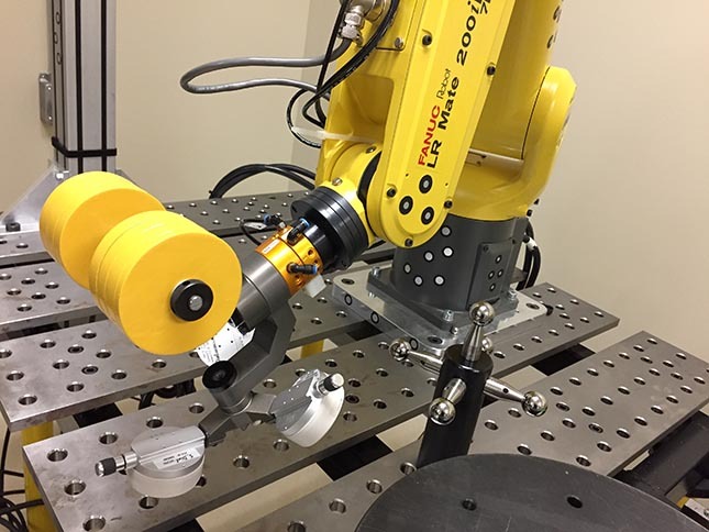
Figure 4 Automated robot calibration using a new 3D measuring device
One problem with robot calibration is that the absolute accuracy of the robot depends not only on the end-effector position but also on the force and torque applied to the end-effector. However, in almost all calibration methods, a maximum load is placed on the robot end-effector (a mass, as in figure 4), so that the force exerted on the robot during measurement is always applied in one direction. To address this deficiency, Professor Bonev and his team have designed a machine that can exert an arbitrary force and torque on the robot effector. This machine is a parallel cable robot (see video 4).
Video 4 Parallel cable robot used to exert the desired force and torque on an industrial robot effector
In the case of a small calibrated robot, the maximum position error can reach 0.5 mm, which is not always sufficiently accurate, especially in the field of aerospace. Another option, a bit more expensive and restrictive, can be used as a last resort. It consists in guiding the robot in real time by constantly measuring the end-effector pose with metrology devices, such as Creaform’s C-Track. CoRo and a team from Concordia University have been working on dynamic guidance methods:
Video 5 Dynamic Path Modification in a Robot
To be continued…
A forthcoming article entitled Real Solutions for Industrial Robotics will introduce Professor Bonev’s other research areas.