Anticipating Risk of Ice Ingestion by Aircraft Engines

Header image purchased on Istock.com. Protected by copyright.
Icing is a significant threat to an aircraft in flight. Ice that forms on the surface of the aircraft weakens its aerodynamic performance and manoeuvrability and can cause accidents. To mitigate this, deicing systems are used to break and remove the ice. However, ice debris directed at the rear of the aircraft can damage the fuselage, or even be sucked in by the engines. This is why, at the design phase, it is advisable to place the engines in an area where the risk of ice block ingestion is low, by anticipating the trajectory of the debris. This article focuses on the digital trajectory simulation of ice debris, or modeling ice debris moving in the airflow. Analyzing the results then makes it possible to estimate where to place the engines during the design phase, to minimize risks of ice block ingestion.
Ice—A Safety Issue
Icy conditions during flight pose a threat to safety. Airborne water droplets adhere to the surface of the aircraft and freeze. In the long run, these conditions can lead to the formation of ice blocks on the wings. This phenomenon is dangerous because the presence of large ice blocks on the aircraft or its components can greatly reduce the lift, or even block mobile control surfaces or sensors.
Figure 1 Wing with ice on its surfaceTo address this problem, deicing systems are installed, for example inflatable air chambers, and are activated to break the ice and “clean” the aircraft surface. This type of deicing, however, presents a danger: broken ice blocks are projected towards the rear of the aircraft and can be sucked in by the engines.
In the preliminary design of a new aircraft model, it is therefore necessary, for safety and certification purposes, to position the engines in an area where there is a low-risk of passing broken ice blocks. Digital simulations are made to pinpoint these areas. Ice block trajectories, once they are dislodged by the air chamber or other systems, are then simulated using a virtual aircraft model.
Predicting Ice Block Trajectories
Research is being done to develop digital simulation models that can predict ice debris trajectories. Among other things, these models will help better position the engines of new aircraft concepts.
Figure 2 Aircraft engineThe main research issue is to correctly model the aerodynamic behaviour of ice debris once broken up. In other words, in which direction will the ice block go considering the air moving around the aircraft? This will depend on the existing forces: lift, drag and gravity. The lift will tend to raise the debris, while the drag will tend to move it in the direction of the moving air. Gravity, on the other hand, will tend to move the debris down. First, a simplifying assumption is used to model the debris as thin spheres or sheets measuring about 10 cm. This is, of course, a simplified view of reality, as ice can take varied and complex shapes.
Once the debris characteristics are established, the simulation program will solve the fundamental principle of dynamics (FPD) applied to ice debris:
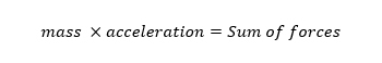
In this case, the forces are lift (only for thin sheet debris), drag and gravity. From this FPD, the position in time of the debris can be calculated: this is its trajectory.
Modeling Spheres
By varying the position, shape, or initial speed of the ice block, it is possible to simulate a large number of trajectories and to obtain a statistical sample. Figure 3 shows trajectory samples for spherical ice blocks from the aircraft wing’s leading edge.
Figure 3 Simulated ice block trajectories around an aircraftAn analysis of this sample makes it possible to define high-risk areas of ice block passages, and also those that present low risks. For example, the previous figure shows a high risk of passing ice blocks below the wing: it is therefore not recommended to place the aircraft engine in that area.
Thin Sheet Modeling
Trajectories of sheet-shaped debris are difficult to model because the rotation speed changes the lift and drag of the sheet. It is necessary to develop new correlations to take into account the rotational character of the debris in the form of thin sheets. Indeed, previous scientific work on the subject did not adequately represent the three-dimensional rotational movement of this type of debris. The proposed model represents the rotational movement using a dynamic moment added to motion equations, which considers the damping effect caused by air. This way, trajectories of sheet debris around the aircraft can be modeled more accurately. In other words, a dynamic damping moment is added to the aerodynamic force moment:
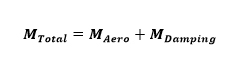
Where Mtotal is the total moment impacting the debris; MAero, the moment generated by the aerodynamic force; and MDamping, the dynamic moment factored in. The dynamic moment takes the following shape, where ρ represents air density, V the relative air velocity around the ice sheet, L and w the length and the width of the sheet respectively, and finally Cx and Cy, the linear moment coefficients per sheet compared to the angular velocity of the sheet (Ignatowicz, 2018):

Risk Areas of Ice Block Ingestion
This new model makes it possible to visualize ice block passages perpendicular to the axis of the aircraft, moving towards the rear. Figure 4 shows a front view of a new aircraft geometry and the risk area for the engines.
Figure 4 Passage of ice blocks at the rear of the aircraftThis sectional view allows once again, by studying the statistical sample, to take into account the risk of ice ingestion when positioning engines on the aircraft.
Conclusion
This type of study will help improve the safety of future aircraft by identifying areas at high risk of ice block impacts early in the design phase, and avoid placing vital aircraft elements like engines or rudders in such areas. Aerodynamic characterization of ice debris is integral to solving the fundamental principle of dynamics.
Additional Information
For more technical details and information on this research work, please refer to Kevin IGNATOWICZ’s Master’s thesis listed in the bibliography (Ignatowicz, 2018).