
Automating Wing Angle Changes inside the LARCASE Price – Païdoussis Wind Tunnel
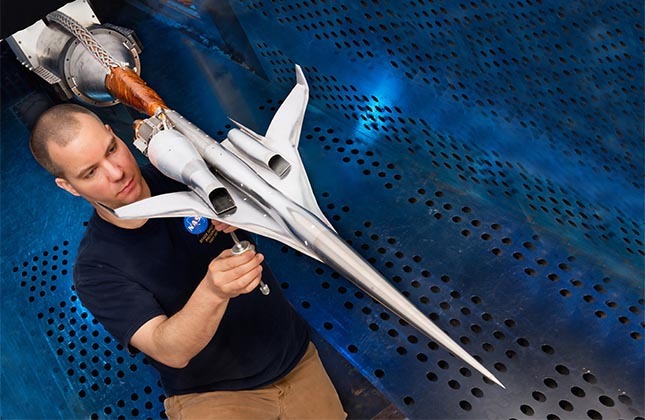
Student researchers at ÉTS designed an aerodynamic balance to automatically rotate parts of their reduced scale models at precise angles inside a wind tunnel in order to calculate lift, drag and moment coefficients. This aerodynamic balance was installed in the subsonic Price-Païdoussis wind tunnel of the Montreal Aeronautical Research Laboratory in Active Control, Avionics and Aeroservoelasticity (LARCASE), at the École de technologie supérieure (ÉTS). The balance significantly reduces the duration of wind-tunnel testing of model reduced scale rotating parts.
Keywords: wind tunnel, aerodynamic balance, test, lift, drag, moment
Introduction
In a wind tunnel, it is necessary to frequently rotate parts at precise angles to calculate lift, drag and moment coefficients. Until recently, the subsonic Price – Païdoussis wind tunnel of the Montreal Aeronautical Research Laboratory in Active Control, Avionics and Aeroservoelasticity (LARCASE), at the École de technologie supérieure (ÉTS), had only a manual system for rotating parts.
Student-researchers from the LARCASE laboratory designed an aerodynamic balance to automatically turn parts and, in this way, greatly reduce the time needed to carry out the required wind tunnel tests.
Designed Aerodynamic Balance
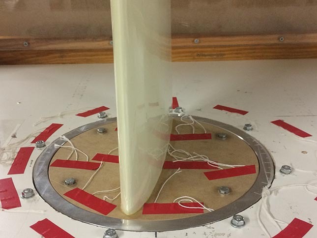
Figure 1 Part of a wing placed on the carrier plate of the balance inside the wind tunnel
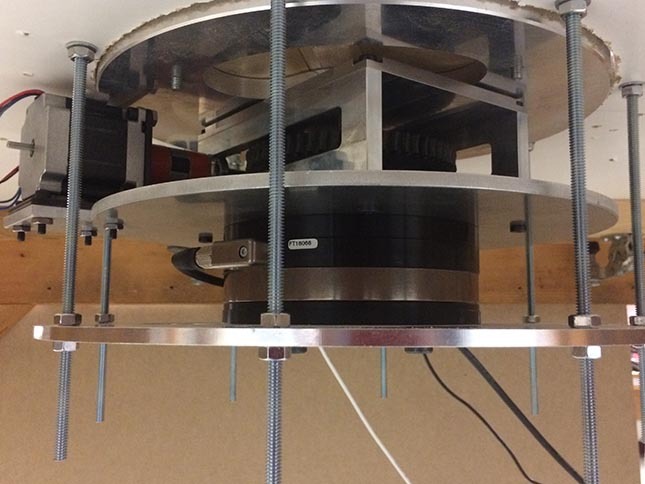
Figure 2 Lower part of the aerodynamic balance
The aerodynamic balance allows automatic rotation of a part placed inside the Price – Païdoussis wind tunnel. This balance was designed and manufactured at ÉTS. Components of the aerodynamic balance are:
- Electric motor
- Housing equipped with a worm screw
- Carrier plate
- Central axis
- Support base.
A control board activates the motor in order to reach a specific position of the rotating part at the selected rotational speed.
Choice of the electrical motor and control board
 The motor had to be affordable and controllable enough to achieve a specific rotation ratio. The control system had to rotate the carrier plate automatically at a specified angle in order to perform wind tunnel tests on an aircraft wing or any other part.
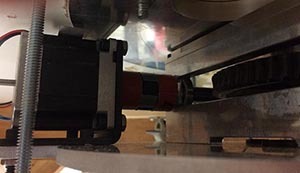
Figure 3 Selected stepper
The characteristics of three types of motors were evaluated: a stepper motor, a direct-current motor and a servomotor. They selected the Phidgets NEMA 23 stepper motor (57STH56 NEMA 23 Bipolar Precision Gearless), that had the desired characteristics, and was affordable (US $28) (Figure 3).
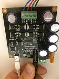
Figure 4 Control board
For this type of motor, the proposed control board is US $95 (PhidgetStepper Bipolar HC) (Figure 4). To control the motor, several computer coding systems can be used: the C, the Python and Java programming languages, or the LabVIEW software. The LabVIEW software is already used to read the forces on the aerodynamic balance: the motor is controlled with this software, which allows the use of one single interface during the tests
.
Parts Modeling
To better visualize the rotation system for the change of angle to be done, modeling of this system was done with the CATIA V5 software. A first assembly was made using a planetary gear. Unfortunately, the gear was too expensive. A second efficient modeling was done using a “wheel and worm screw” type of gear.
The motor rotates the horizontal axis, causing the attached “worm screw” to rotate. The teeth of the worm screw insert in the grooves between the teeth of the wheel, activating its rotation (FIG. 5).
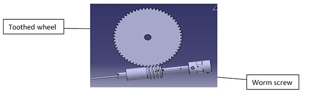
Figure 5 Operating principle of the worm screw
The central axis is connected to the toothed wheel, and also to the carrier plate (Figure 6). In this way, the plate can rotate correctly. To complete the system, the parts can be easily assembled.
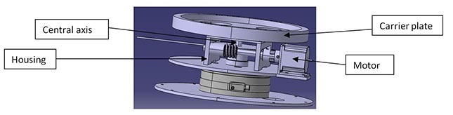
Figure 6 Assembly drawing of the main parts of the aerodynamic balance
Motor Control
To facilitate the use of the aerodynamic balance, a user interface designed with the LabVIEW software is supplied with the motor. It is a control panel with cursors used to vary the position, speed and acceleration of the motor (Figure 7).
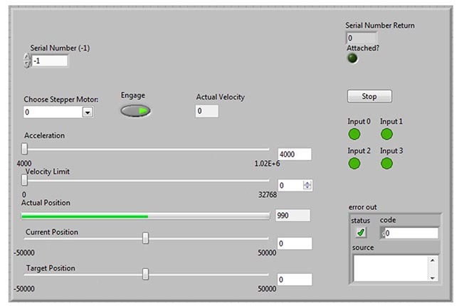
Figure 7 User interface of the control panel
Grâce à cette automatisation, les variations d’angle se font à partir d’un ordinateur de la salle de soufflerie, rendant les tests plus rapides. En effet, nous pourrons effectuer les mesures de 30 angles et 4 vitesses d’air dans la soufflerie en moins de 30 minutes. Auparavant, ces tests auraient nécessité plus de 9 heures en changeant d’angles manuellement.
Figure 8 David Communier, PhD student and Antoine Machetto, Bachelor’s in Engineering student, in front of the wind tunnel test section chamber


